Project Video
I selected the Harbin Cultural Center in Harbin, China as my target model. Since there is only perspectives and roof plan as reference, I can only roughly build the form of the building.

Top view of the building

Roof plan of the target building
2. Modeling
2.1 First Layer
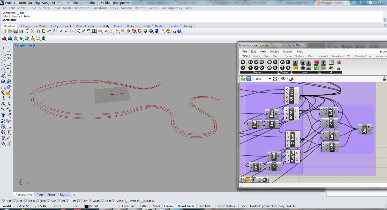
Based on the roof plan of the target building, I drew the outline of first layer as my basic curve.

Then I used offset and move node to create the boundary of first layer.

I lofted each two of these four curves together, and joined these four lofted surface into a Brep as the first layer.

The direction and height of first layer can be changed by the following parameters.


2.2 Second Layer
Similarly, I built the second layer. The only difference is that I have to choose the subcurve from the basic curve, using the shatter node.

I also have to redraw the Nurbs curve to control the form of the second layer.

I got the boundary of second layer.

I lofted each two of these four curves together, and joined these four lofted surface into a Brep as the second layer.

The location, length, width, and direction of second layer can be changed by the following parameters.

2.3 Third Layer
The third layer is similarly built as the second layer. I have to choose two subcurves from the basic curve, and connect a rotated curve with these two subsurves to create a new basic curve.

I redrew the connected curve using Nurbs curve to guarantee the continuity.

Similarly, I use the offset and rotate node the create the boundary of third layer.
And I lofted each two of these four curves together, and joined these four lofted surface into a Brep as the third layer.

The length, width, and direction of third layer can be changed by the following parameters.

2.4 Roof Paneling
I use one curve from third layer as reference.

Then I used curve closet point to a portion of the reference curve.

Then I used the two end points of the previous curve and the moved mid-point of these two end points as three control points to create a Nurbs curve.

I used Edge Surface node to create a surface according to these two curves.

Then I used Divide Surface node, Interpolate Curve and Pipe node to create roof paneling.

Similarly, I created the other roof paneling.

The position and form of roof paneling can be changed by the following parameters.

2.5 Final Model

3. Physically-based Model
I used Kangaroo, Springs, and UForce (gravity) to add gravity force on the roof.

Toggle: True

Toggle: False
4. Curvature Analysis
Since all my model is based on curves, curvature of basic curves are very importance to the model.
Thus, I analyzed each reference curve of these three layers to get every point's curvature on the curve.

First Layer

Second Layer

Third Layer
5. Perspective


